Flipper Zero and My Patio Lights
05 Jan 2023 - pdavid
Having a massive (100ft) LED strip for my patio lights was a big goal when we moved into our new apartment. But we really wanted to have a little more flexibility than provided by the built-in (RF-only) controller. Using the Flipper Zero, I was able to eventually capture all the remote’s buttons to control the lights with a Raspberry Pi Pico W, a CC1101 module, and a lot of trial and error.

Overall Stages of Development
- 1 - Overview of Setup & Parts Used
- 2 - Recording the Remote Buttons
- 3 - Research of Signal Protocols
- 4 - CC1101 & Pico W Setup
- 5 - Transmitting w/ Micropython
- 6 - Trying again w/ Arduino C++
- 7 - Pretending at Signal Analysis
- 8 - Refining Signal Data Storage
- 9 - Attempting to Use a Preamble
- 10 - Good Enough!
- 11 - Random Insight into LED Strip Behavior
- 12 - Finally Encoding Original Recordings
- 13 - Post-project follow-ups
1 - Overview of Setup & Parts Used 
For this project, I had an already existing customized 100-foot long RGB light strip. The customization is probably good for a post on its own, but at a high level, the lighting came with a waterproof LED strip, an RF controller, and an RF remote control. Unfortunately the LED strip wasn’t waterproof, so I customized it by building the controller into a waterproof box and extending the power cord so I could leave it out on my porch through all weather conditions without any major concerns.
I’d also just recently gotten into poking at Raspberry Pi Picos. I’d used Arduinos and Particle Argons in the past on projects but liked the idea of running Python on a microcontroller because I’m more familiar with Python than C++. (You’ll see why that didn’t work out for this project soon. Ah, well.) So I figured I’d go RPi Pico W with the CC1101 transceiver (the same one that’s in the Flipper Zero). I had already experimented a bit and figured out that the Flipper can emulate the remote, so I knew having the same transceiver would allow me to do it myself if I could figure it out.
1.1 - Parts List
- LED Light Strip
- Brillihood 100ft/30m RGB Neon Rope Light Link
- Required Items - RF Transmitter
- Optional Items - Debugging / prototyping
I listed the GeeekPi board as temporary because I could go through and build a case for my RF transmitter setup. I have not done so, since it was very very very late at night when I got everything working and I now have it all still connected using the GeeekPi board. It’ll probably stay that way until after the holidays.
2 - Recording the Remote Buttons 
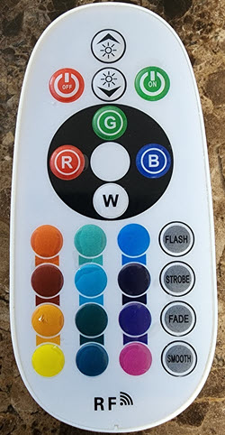
This is the remote that I attempted to emulate. It’s a standard RF no-brand remote that comes with tons of different LED strips. Honestly, the colors mostly didn’t match the actual light strip when lit, but since I wasn’t using it for color fidelity checks, it was good enough for me.
So, there’s a lot of stuff already written on using the Flipper Zero for recording RF signals. I basically read this, assumed I knew everything I needed to know, and just pressed buttons until I got something to work.
2.1 - Finding the frequency of the remote
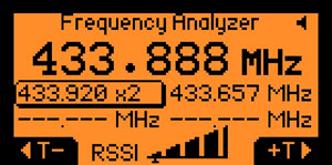
I started with the sub-GHz frequency analyzer, which happened to default to an AM frequency that showed up with my remote. I started the analyzer, and pressed a few of the remote buttons. When doing so, it popped up at ~433MHz, so I was pretty positive that if the analyzer could see it, I could (at worst) read the raw signal and play it back. At best, it could decode whatever the signal is and provide me the protocol to use, simplifying the full remote’s emulation.
2.2 - Recording the raw signals
Once I knew the frequency, I switched to Flipper’s Read RAW mode to verify if it’s capable of playing back a signal. I started the recorder and pressed the orange light button remote, then stopped the recorder and saved it to the Flipper. It showed me a spike on the screen, so I assumed everything was good.

Then I changed the light strip to another color, and used Flipper’s Send mode to play it back. The light changed, meaning the CC1101 chip worked! So, I now had my fallback plan confirmed to be an option. Since I’ll be using the signal from another device, I grabbed the raw recording file from the Flipper.
Filetype: Flipper SubGhz RAW File
Version: 1
Frequency: 433920000
Preset: FuriHalSubGhzPresetOok650Async
Protocol: RAW
RAW_Data: 60824 -66 40307 -64 19889 -100 1757 -66 1089 -66 12747 -100 11829 -68 32647 -66 7033 -17380 67 -1260 199 -132 65 -198 131 -100 131 -132 297 -134 67 -630 199 -66 233 -132 399 -134 399 -130 165 -396 14485 -100 4061 -66 2219 -66 23345 -66 72679 -100 33233 -66 62597 -66 44711 -66 12647 -66 11759 -98 10387 -66 3897 -68 529 -98 889 -66 50761 -66 229 -68 17053 -64 21881 -2366 249 -808 283 -804 247 -828 255 -824 225 -840 233 -830 835 -240 845 -240 279 -800 833 -276 809 -276 243 -804 271 -796 837 -276 245 -802 269 -798 835 -276 245 -808 269 -796 271 -802 837 -276 243 -806 833 -240 277 -804 271 -10862 267 -798 269 -800 271 -800 271 -802 269 -800 271 -802 835 -276 813 -240 279 -804 833 -240 845 -240 279 -804 271 -798 833 -276 245 -804 269 -798 835 -276 245 -806 269 -796 271 -804 835 -274 245 -804 835 -240 279 -802 269 -10846 275 -806 267 -800 271 -804 271 -800 269 -800 271 -802 835 -276 815 -240 279 -800 835 -240 845 -274 245 -804 269 -798 833 -276 245 -802 271 -800 835 -276 245 -804 269 -798 269 -806 833 -276 245 -804 833 -276 243 -806 269 -10862 269 -794 271 -800 269 -800 271 -800 271 -804 269 -802 835 -276 813 -240 279 -802 833 -276 811 -242 279 -802 269 -798 835 -276 245 -806 269 -798 837 -274 245 -804 271 -798 269 -800 835 -276 245 -806 831 -276 245 -806 269 -10856 269 -798 271 -800 271 -802 271 -802 271 -798 271 -804 837 -276 811 -274 245 -802 833 -276 811 -276 243 -802 269 -798 835 -276 245 -808 269 -796 835 -276 245 -806 267 -798 271 -806 835 -276 245 -802 833 -276 243 -806 269 -10858 267 -796 269 -802 269 -804 271 -800 271 -800 271 -804 833 -276 811 -274 245 -802 833 -276 811 -274 243 -806 269 -796 835 -276 243 -808 269 -796 835 -274 247 -804 269 -798 269 -804 837 -274 245 -804 833 -242 277 -804 267 -162736 99 -1118 363 -100 195 -264 229 -360 97 -200 755 -66 6811 -100 5675 -66 6373 -98 13705 -66 14751 -68 54237 -66 32119 -66 1531 -66 5249 -68 6397 -66 44515 -100 15541 -66 10517 -68 27293 -68 20539 -66 13969 -66 657 -66 3239 -98 20847 -68 14209 -66 14423 -100 42891 -100 4619 -100 24811 -66 4341 -66 10131 -66 34427 -66 13497 -2410 231 -826 269 -798 269 -802 269 -802 271 -802 271 -800 835 -274 811 -276 243 -804 837 -276 777 -308 243 -802 271 -798 837 -276 243 -802 269 -800 833 -276 245 -806 269 -800 271 -802 833 -276 243 -804 837 -276 243 -802 271 -10832 299 -796 269 -802 269 -800 269 -802 271 -804 271 -800 835 -276 813 -240
RAW_Data: 279 -804 835 -238 847 -240 279 -800 269 -798 835 -276 245 -806 269 -800 833 -276 245 -806 269 -798 269 -804 833 -276 245 -806 833 -276 243 -806 269 -10860 269 -796 271 -800 271 -804 269 -798 271 -800 271 -802 839 -276 811 -240 279 -802 831 -276 811 -240 279 -806 269 -798 835 -276 243 -804 269 -800 835 -276 243 -804 269 -800 271 -804 835 -274 245 -804 833 -276 243 -804 269 -10866 269 -794 271 -802 271 -800 269 -802 271 -800 271 -802 833 -276 813 -240 281 -806 833 -240 845 -240 279 -802 269 -800 835 -240 281 -802 269 -798 837 -240 281 -802 269 -798 271 -804 837 -240 279 -804 833 -276 243 -804 271 -10838 273 -812 273 -802 269 -798 271 -800 271 -806 271 -800 835 -276 809 -276 243 -802 833 -276 815 -238 279 -802 269 -800 835 -276 245 -804 269 -798 833 -276 245 -806 269 -800 271 -802 833 -276 245 -806 833 -276 243 -804 269 -10862 267 -798 269 -802 269 -802 271 -804 271 -800 271 -802 835 -242 849 -240 279 -800 837 -240 813 -272 279 -802 269 -796 835 -276 245 -804 269 -804 833 -242 279 -802 269 -800 269 -802 839 -240 279 -804 831 -276 243 -804 269 -10864 267 -796 269 -800 271 -804 271 -802 269 -802 271 -802 837 -276 811 -240 277 -802 833 -276 811 -240 279 -806 269 -798 837 -242 277 -806 269 -798 835 -274 245 -804 269 -800 269 -802 835 -276 245 -806 833 -274 245 -806 269 -151972 97 -4654 97 -332 97 -398 101 -300 561 -200 131 -296 1051 -66 395 -98 16079 -98 6381 -100 2271 -66 24421 -100 4581 -66 5445 -66 53953 -100 635 -66 9491 -66 11621 -66 15277 -66 7187 -66 22515 -68 2087 -66 21043 -66 2097 -68 11031 -66 13553 -64 14697 -66 1949 -66 4535 -64 13145 -100 3909 -98 31109 -66 33191 -66 1055 -98 31927 -100 14507 -66 3491 -68 41109 -100 4841 -100 12273 -130 5665 -66 14269 -2432 243 -854 209 -850 207 -850 239 -844 239 -840 237 -836 801 -274 811 -274 245 -840 773 -306 775 -306 243 -804 269 -834 803 -276 245 -808 269 -800 835 -276 245 -804 269 -798 269 -802 841 -274 243 -806 833 -274 243 -806 269 -10862 269 -796 269 -802 271 -804 271 -800 269 -802 271 -802 839 -240 845 -240 279 -802 835 -240 847 -238 279 -802 269 -800 837 -274 245 -806 269 -798 837 -276 243 -804 269 -800 269 -804 837 -276 243 -804 831 -276 243 -804 269 -10860 271 -798 271 -800 269 -804 271 -804 269 -800 269 -802 837 -278 809 -240 279 -802 835 -276 809 -276 243 -806 269 -798 835 -276 243 -804 269 -800 835 -276 245 -808 267 -798 271 -800 837 -276 245 -806
RAW_Data: 833 -274 245 -806 269 -10860 269 -796 269 -800 271 -802 271 -802 271 -802 269 -802 835 -276 813 -274 245 -804 837 -240 811 -272 279 -800 269 -800 835 -276 245 -804 269 -798 835 -276 245 -808 269 -796 271 -802 835 -276 243 -806 833 -276 243 -806 269 -10846 273 -804 269 -798 271 -804 271 -802 271 -800 269 -802 837 -276 811 -276 243 -802 833 -276 811 -240 279 -804 269 -800 835 -274 245 -804 269 -800 835 -276 245 -804 267 -798 271 -804 835 -276 247 -802 835 -274 245 -804 269 -10834 311 -776 269 -802 271 -802 269 -804 271 -800 271 -802 835 -274 811 -276 243 -806 835 -240 813 -272 279 -800 269 -798 837 -276 245 -808 269 -796 835 -276 245 -806 269 -796 269 -802 837 -276 245 -806 833 -274 243 -802 269 -10830 299 -798 269 -800 269 -802 269 -804 271 -800 271 -802 833 -276 813 -276 245 -806 835 -238 845 -238 279 -802 269 -798 837 -274 245 -806 269 -800 837 -240 277 -804 269 -798 269 -804 835 -242 279 -802 833 -274 245 -806 269 -10856 269 -798 269 -798 273 -802 269 -804 271 -800 271 -800 835 -276 815 -242 277 -800 833 -242 845 -240 279 -804 269 -798 833 -276 247 -804 269 -798 839 -242 279 -800 269 -800 269 -802 837 -242 279 -804 831 -276 243 -806 271 -156402 65 -2070 197 -658 197 -330 399 -66 2057 -66 13031 -66 32069 -68 20585 -66 1155 -66 1447 -98 62557 -66 21729 -68 4611 -66 265 -70 15155 -132 41377 -66 5847 -66 21199 -100 4543 -66 27103 -66 20797 -66 12089 -98 2227 -64 11073 -100 14169 -66 291 -100 16019 -98 20827 -100 5967 -66 13193 -64 12851 -68 5493 -66 44611 -66 10141 -2414 231 -858 201 -862 201 -866 237 -838 237 -836 239 -834 767 -306 811 -274 245 -808 801 -306 779 -308 243 -804 269 -832 801 -276 243 -808 269 -798 835 -274 245 -804 269 -802 271 -802 833 -276 243 -838 801 -276 243 -806 269 -10852 273 -804 269 -802 271 -802 269 -802 269 -802 271 -804 835 -276 809 -276 243 -806 833 -276 809 -276 243 -806 269 -798 833 -276 245 -808 269 -800 835 -276 243 -804 271 -796 271 -800 837 -276 245 -804 833 -274 245 -804 269 -10846 273 -806 271 -802 269 -802 271 -804 269 -800 271 -802 837 -240 849 -240 279 -800 835 -240 845 -274 243 -804 269 -798 837 -276 243 -804 271 -800 837 -240 279 -802 269 -798 273 -802 833 -276 245 -804 833 -274 245 -804 269 -10858 269 -798 269 -804 269 -802 271 -802 271 -800 271 -802 833 -276 815 -240 277 -802 833 -276 811 -240 279 -802 267 -798 837 -276 245 -806 269 -798 835 -274 245 -808 269 -796
RAW_Data: 269 -800 835 -276 245 -808 833 -240 279 -802 269 -10848 271 -806 269 -800 271 -804 269 -800 271 -802 271 -802 835 -242 847 -240 279 -802 833 -240 849 -240 277 -802 269 -798 833 -276 245 -806 269 -798 835 -276 245 -804 269 -798 271 -804 833 -276 245 -808 831 -274 243 -804 267 -10864 269 -794 271 -800 271 -800 269 -800 271 -802 271 -804 837 -242 813 -272 277 -802 833 -276 813 -240 277 -802 269 -798 835 -276 245 -806 271 -798 833 -278 243 -806 269 -800 271 -798 835 -276 245 -806 835 -276 245 -802 269 -10862 267 -796 271 -798 271 -800 271 -804 271 -800 269 -802 835 -242 847 -240 281 -802 835 -240 843 -240 279 -804 267 -798 839 -240 279 -802 271 -796 837 -276 243 -804 271 -798 269 -804 837 -242 277 -802 835 -274 245 -804 269 -10834 313 -778 271 -800 271 -800 269 -802 269 -802 271 -804 835 -278 809 -240 279 -802 835 -274 811 -274 245 -804 269 -800 835 -276 243 -804 269 -798 837 -276 245 -806 269 -800 269 -798 835 -276 245 -806 837 -240 277 -802 267 -10850 273 -806 271 -796 271 -802 271 -802 271 -800 271 -802 837 -240 849 -240 277 -800 833 -242 845 -240 281 -804 269 -796 835 -276 245 -804 269 -798 835 -276 245 -808 271 -796 269 -802 837 -242 277 -804 837 -240 279 -802 267 -158018 65 -266 65 -398 131 -230 163 -132 163 -1414 197 -98 557 -98 24823 -100 12721 -66 18257 -68 7261 -98 821 -66 34275 -66 35535 -66 7895 -100 14163 -68 21917 -198 31261 -66 5089 -98 53039 -96 1097 -66 25829 -66 10131 -66 5671 -66 14321 -66 11783 -66 6483 -168 17811 -100 66343 -100 30299 -134 393 -66 15663 -17214 65 -1380 65 -1286 165 -428 661 -100 563 -66 299 -66 431 -198 1247 -66 1417 -66 4719 -66 165 -68 9227 -66 2063 -100 4919 -98 12125 -66 11585 -100 15539 -100 5431 -66 13403
2.3 - Recording decoded signals
For my easiest method of emulating the remote, I’d prefer the decoded signals. This would prevent trimming and cleaning up the raw signal recordings to get the noise out, and would mean I could use a simple hex number or string (depending on the sent data). So now I moved to trying to use Flipper’s Read functionality.
I repeated the same way as the raw recording: Start listening, press the orange button, and when it detected it and decoded, I stopped the recording and saved the file. I used Send to play it back, and it correctly changed the lighting back to orange.

Since it decoded something successfully, I went through and recorded all the buttons. They were all the same format, with a few bytes of hex different, so that was promising.
Filetype: Flipper SubGhz Key File
Version: 1
Frequency: 433920000
Preset: FuriHalSubGhzPresetOok650Async
Protocol: Princeton
Bit: 24
Key: 00 00 00 00 00 03 64 8A
TE: 268
If I could emulate one of them from the protocol, I could possibly emulate all of them based on their bytes as opposed to dealing with raw signals. That’s some positive motion!
3 - Research of Signal Protocols 
Okay, so here’s the first real misdirection that I took. The information I gathered from here was beneficial in helping understand what’s possible, but honestly was otherwise a large time sink for not much output. Here’s the summary takeaways that were beneficial:
- I couldn’t find a solid explanation of the
Princeton 24-bitprotocol that Flipper refers to. Maybe some other people know what this is, but I was unable to find any real details on how this results in actual raw signal transmissions. This meant I was going to have to write my own protocol encoder due to lack of knowledge on where to find support.- The protocol refers to some
ASKOOKportion of the protocol. TheASKwas easily researched as “amplitude shift keying” and theOOKwas a more specific version ofASKknown as “on-off keying”. This meant that I wasn’t dealing with a frequency modulation at all, but just an on/off signal. If I was able to turn the radio on and off properly, the signal could be emulated.- The CC1101 chip supports synchronous mode and asynchronous mode for transmission / reception. I’m ignoring the reception since the receiver will actually be the LED strip controller out on my porch. But to finely control the transmission to match my signals I would have to use the async mode. Without protocol details, I couldn’t rely on using the synchronous setup and letting the CC1101 handle a specific protocol.
- Flipper’s RAW signal encoding is actually very simple: A string of integers with positive numbers meaning HIGH and negative numbers meaning LOW/OFF. The integers are a measure of microseconds that the signal was at that level. So a RAW signal of
100 -200 100means ON for 100 microseconds, off for 200 microseconds, and on again for 100 microseconds. Using async mode, this is really do-able via a microcontroller if we just paste in the raw signals as an array.
So net result was that I’d have to go back and plan on using the raw signal mode for now, and see if I can get that working.
4 - CC1101 & Pico W Setup
There’s a lot of different sites that discuss using the CC1101 chip with arduinos, Raspberry Pis, and other controllers. However, none of them discussed using them with an Raspberry Pi Pico. I also noticed that my CC1101 chip had 8 pins instead of the 10 most of the examples I saw were done with. I found this comment on a different CC1101 transceiver which seemed to provide an 8-pin pinout:
| # | Pin | # | Pin |
|---|---|---|---|
| 1 | GND | 2 | VCC |
| 3 | GDO0 | 4 | CSN |
| 5 | SCLK | 6 | SDI |
| 7 | SDO | 8 | GDO2 |
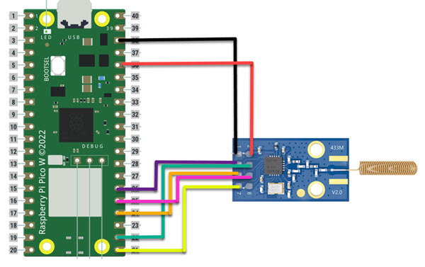
So, using this pinout and my Pico W, I did the following wiring using the GeeekPi Board to allow me to see activity on the different pins while working on the software side.
| # | CC1101 | PicoW | # | CC1101 | PicoW |
|---|---|---|---|---|---|
| 1 | GND | GND | 2 | VCC | 3v3 |
| 3 | GDO0 | GPIO20 | 4 | CSN | GPIO17 |
| 5 | SCLK | GPIO18 | 6 | SDI | GPIO19 |
| 7 | SDO | GPIO16 | 8 | GDO2 | none |
I chose to use the default SPI0 setup on the Pico W (at the time - it’s since been moved to lower GPIO pins). I also used GDO0 on GPIO20 just to keep all the wiring together and allow for more tight cabling in a more permanent setup once done working on the emulation.
5 - Transmitting w/ Micropython 
Since I was working on a transmit-only project, I was fine using the sample CC1101 micropython library for testing, but would have to modify it to properly operate in a raw, GDO0-driven mode. I came across this library by Martin Winter, and figured I could at least use the library to verify if my wiring was working properly. I loaded up my Flipper in Read RAW mode and ran the example program, and saw a spike. Hooray! The wiring was good!
I then went about trying to understand the raw library, and it was, to say the least, mostly incomprehensible. Not because of the library itself, but because of the large number of variables that are involved in configuring the CC1101 chip itself. The first 100+ lines of the library are basically just defining all the addresses of the different chip settings, and later in the library is a regConfigSettings method that configures the chip for the FIFO-based transmission the library is setup to use. I could modify the configuration of the library locally in my project by just updating this method with whatever appropriate settings are needed.
Lots of searching around the internet, including reading the majority of the configuration tables and options for the chip found in the data sheet gave me an idea of several of the settings needed to be modified, but no matter what I did, I could not get it to transmit ANYTHING in response to a high-signal on the GDO0 pin. I even went so far as to attempt to use the TI SmartRF Flash Programmer tool to attempt to export out all the correct settings, and that still didn’t get a functional working transmission.
I basically threw in the towel in the MicroPython effort here, as I was unable to come up with a working solution. I clearly didn’t know enough about what I was doing.
6 - Trying again w/ Arduino C++
So, giving up on the MicroPython meant I had to revert back to C++, Arduino-style. I’m honestly terrible at C++, but it’s a programming language, so I can make do. By moving to C++, I was able to find a clear GDO0-driven example which I could cannibalize for my purposes. This project by Simon Dankelmann had a great example of using the raw Flipper signals to transmit via the async GDO0 setup, which is steps away from what I wanted.
The file read raw flipper files from an SD card and transmitted all of them. Since I’m not using an SD card, I had to translate what the example was doing and to pass in an array for the raw format. So I basically ripped out the sendSamples method and a bunch of the setup stuff. Basically, Simon seemed to have figured out all the CC1101 settings that I needed and configured that using the SmartRC library by LSatan.
// These examples are from the Electronics Cookbook by Simon Monk
// https://github.com/LSatan/SmartRC-CC1101-Driver-Lib
// mod by Little_S@tan
// Usage & Configuration by Simon Dankelmann
// https://github.com/simondankelmann/Esp32-SubGhz/blob/main/Esp32/Esp32-SubGhz/Esp32-SubGhz.ino

#include <ELECHOUSE_CC1101_SRC_DRV.h>

#define CCGDO0 20 //GPIO20
#define CCGDO2 21 //GPIO21
int btn1x1code [512] = {60824, -66, 40307, -64, 19889, -100, 1757, -66, 1089, -66, 12747, -100, 11829, -68, 32647, -66, 7033, -17380, 67, -1260, 199, -132, 65, -198, 131, -100, 131, -132, 297, -134, 67, -630, 199, -66, 233, -132, 399, -134, 399, -130, 165, -396, 14485, -100, 4061, -66, 2219, -66, 23345, -66, 72679, -100, 33233, -66, 62597, -66, 44711, -66, 12647, -66, 11759, -98, 10387, -66, 3897, -68, 529, -98, 889, -66, 50761, -66, 229, -68, 17053, -64, 21881, -2366, 249, -808, 283, -804, 247, -828, 255, -824, 225, -840, 233, -830, 835, -240, 845, -240, 279, -800, 833, -276, 809, -276, 243, -804, 271, -796, 837, -276, 245, -802, 269, -798, 835, -276, 245, -808, 269, -796, 271, -802, 837, -276, 243, -806, 833, -240, 277, -804, 271, -10862, 267, -798, 269, -800, 271, -800, 271, -802, 269, -800, 271, -802, 835, -276, 813, -240, 279, -804, 833, -240, 845, -240, 279, -804, 271, -798, 833, -276, 245, -804, 269, -798, 835, -276, 245, -806, 269, -796, 271, -804, 835, -274, 245, -804, 835, -240, 279, -802, 269, -10846, 275, -806, 267, -800, 271, -804, 271, -800, 269, -800, 271, -802, 835, -276, 815, -240, 279, -800, 835, -240, 845, -274, 245, -804, 269, -798, 833, -276, 245, -802, 271, -800, 835, -276, 245, -804, 269, -798, 269, -806, 833, -276, 245, -804, 833, -276, 243, -806, 269, -10862, 269, -794, 271, -800, 269, -800, 271, -800, 271, -804, 269, -802, 835, -276, 813, -240, 279, -802, 833, -276, 811, -242, 279, -802, 269, -798, 835, -276, 245, -806, 269, -798, 837, -274, 245, -804, 271, -798, 269, -800, 835, -276, 245, -806, 831, -276, 245, -806, 269, -10856, 269, -798, 271, -800, 271, -802, 271, -802, 271, -798, 271, -804, 837, -276, 811, -274, 245, -802, 833, -276, 811, -276, 243, -802, 269, -798, 835, -276, 245, -808, 269, -796, 835, -276, 245, -806, 267, -798, 271, -806, 835, -276, 245, -802, 833, -276, 243, -806, 269, -10858, 267, -796, 269, -802, 269, -804, 271, -800, 271, -800, 271, -804, 833, -276, 811, -274, 245, -802, 833, -276, 811, -274, 243, -806, 269, -796, 835, -276, 243, -808, 269, -796, 835, -274, 247, -804, 269, -798, 269, -804, 837, -274, 245, -804, 833, -242, 277, -804, 267, -162736, 99, -1118, 363, -100, 195, -264, 229, -360, 97, -200, 755, -66, 6811, -100, 5675, -66, 6373, -98, 13705, -66, 14751, -68, 54237, -66, 32119, -66, 1531, -66, 5249, -68, 6397, -66, 44515, -100, 15541, -66, 10517, -68, 27293, -68, 20539, -66, 13969, -66, 657, -66, 3239, -98, 20847, -68, 14209, -66, 14423, -100, 42891, -100, 4619, -100, 24811, -66, 4341, -66, 10131, -66, 34427, -66, 13497, -2410, 231, -826, 269, -798, 269, -802, 269, -802, 271, -802, 271, -800, 835, -274, 811, -276, 243, -804, 837, -276, 777, -308, 243, -802, 271, -798, 837, -276, 243, -802, 269, -800, 833, -276, 245, -806, 269, -800, 271, -802, 833, -276, 243, -804, 837, -276, 243, -802, 271, -10832, 299, -796, 269, -802, 269, -800, 269, -802, 271, -804, 271, -800, 835, -276, 813, -240}

void initCC1101(){
  ELECHOUSE_cc1101.setSpiPin(18, 16, 19, 17); // (SCK, MISO, MOSI, CSN);
  ELECHOUSE_cc1101.Init();
  ELECHOUSE_cc1101.setGDO(CCGDO0, CCGDO2);
  ELECHOUSE_cc1101.setMHZ(433.92);        // Here you can set your basic frequency. The lib calculates the frequency automatically (default = 433.92).The cc1101 can: 300-348 MHZ, 387-464MHZ and 779-928MHZ. Read More info from datasheet.
  ELECHOUSE_cc1101.setPA(12);
  ELECHOUSE_cc1101.SetTx();               // set Transmit on
  ELECHOUSE_cc1101.setModulation(2);      // set modulation mode. 0 = 2-FSK, 1 = GFSK, 2 = ASK/OOK, 3 = 4-FSK, 4 = MSK.
  ELECHOUSE_cc1101.setDRate(512);         // Set the Data Rate in kBaud. Value from 0.02 to 1621.83. Default is 99.97 kBaud!
  ELECHOUSE_cc1101.setPktFormat(3);       // Format of RX and TX data. 0 = Normal mode, use FIFOs for RX and TX.
                                          // 1 = Synchronous serial mode, Data in on GDO0 and data out on either of the GDOx pins.
                                          // 2 = Random TX mode; sends random data using PN9 generator. Used for test. Works as normal mode, setting 0 (00), in RX.
                                          // 3 = Asynchronous serial mode, Data in on GDO0 and data out on either of the GDOx pins.
  if(!ELECHOUSE_cc1101.getCC1101()){       // Check the CC1101 Spi connection.
    Serial.println("CC1101 Connection Error");
  }
}


void setup() {
    Serial.begin(9600);
    initCC1101();
}

void loop() {
  sendSamples(btn1x1code, 512);
  delay(2000);
}

void sendSamples(int samples[], int samplesLength) {
  int totalDelay = 0;
  unsigned long time;
  byte n = 0;

  for (int i=0; i < samplesLength; i++) {
    // TRANSMIT
    n = 1;

    totalDelay = samples[i]+0;
    if(totalDelay < 0){
      // DONT TRANSMIT
      totalDelay = totalDelay * -1;
      n = 0;
    }

    digitalWrite(CCGDO0,n);
    delayMicroseconds(totalDelay);
  }
  // STOP TRANSMITTING
  digitalWrite(CCGDO0,0);
}
When ran on the Pico, it worked! I saw the signal on Flipper’s raw recorder. I also noticed that my patio lights flipped to orange, so it definitely transmitted the raw signal successfully!
I could leave the project here, and simply record the red and green button signals, translate them to C++ arrays like the sample above, and then play them back on a loop, but that sounded like a lot of work. It also didn’t really get me something that I could use in the future, as I’d have to record ALL of the buttons on the remote and the signals probably recorded noise that I’m now replaying every time, etc. etc. etc. So let’s now start cleaning up this hot mess that I got working.
7 - Pretending at Signal Analysis 
Now tht I know I can replay the raw signals, I wanted to isolate out the clear signal in the noise of the full RAW recording. This would allow me to send the signals as fast as possible without the dead air that was at the beginning and end as I manually started and stopped recording on the Flipper.
So going back to the RAW recording file, I made a couple assumptions and worked from there:
- There will be a large NEGATIVE area in the RAW file format at the beginning and end of the actual signal. The remote should be NOT sending when the button isn’t pressed, so in theory, the signal should be all NEGATIVE and then whatever +-+-+- pattern for the signal, and then all NEGATIVE when done.
- If I trim off something important from the actual signal, the patio lights will not respond when played back. So I would guess at areas of the signal to delete out, replay and see if the patio responds. If it does, I didn’t trim out anything important. If it doesn’t respond, then something in what I deleted was important and I should try trimming a smaller bit out.
Using these two assumptions, I started by just eyeballing for large numbers and seeing if they were negative. Unfortunately for me, background noise shows up in the raw recording as positive and negative numbers, and since amplitude isn’t captured, it’s hard to tell what is valid. So I searched for large 5+ digit numbers that are negative using regex, and started trimming. Eventually, I was able to trim the signal down to a short (~50 segment) string of integers through sheer trial and error.
Filetype: Flipper SubGhz RAW File
Version: 1
Frequency: 433920000
Preset: FuriHalSubGhzPresetOok650Async
Protocol: RAW
RAW_Data: 249 -808 283 -804 247 -828 255 -824 225 -840 233 -830 835 -240 845 -240 279 -800 833 -276 809 -276 243 -804 271 -796 837 -276 245 -802 269 -798 835 -276 245 -808 269 -796 271 -802 837 -276 243 -806 833 -240 277 -804 271 -10862
I cleaned that up and got it into my code. I left it running on my Pico to just emulate the button press every two seconds, and it… didn’t always work. It worked a lot, but not always. I went back to the raw file to try to figure out why it wasn’t always working and noticed something else. There was a consistently long NEGATIVE segment right at the end of the signal, but I saw a (close to) same length NEGATIVE segment four more times in the original button press signal. So I suspected that there was a repeated transmission going on on each button press. I updated my code to loop 5 times to match, and I saw a marked impovement in reliability of the patio responding. It would still flake out a bit, but not nearly as much.
Now that I know I have a mostly working chunk of signal, and that it repeated, I had something I really wanted to fix. I’ve been pasting in a RAW array of integers that were recorded, and the trimming trial and error was very, very slow. I didn’t want to do that too much, but also I knew that the recording is a lossy function. I suspected I had repeated signals, but I didn’t actually see any real repeating sequences in the Flipper RAW file, so I knew that the signal wasn’t actually clean.
8 - Refining Signal Data Storage
I was looking at the data and realized something else. There was a part of the DECODED Flipper file I wasn’t sure what it meant exactly, and I couldn’t find anything specific about it. Specifically, it was the TE: 268 line. There was an interesting thing about it though. It seemed to be pretty close to a lot of the integers in the RAW recording that I trimmed down. Specifically, I was seeing a lot of “close to 268” values. I also checked and 3x268=804, so I was also seeing a lot of those too in the signal. As you can see below, it’s pretty consistently a 3 or a 1. The extra on the end I considered just the normal start / stop of the signal.
RAW_Data: 249 -808 283 -804 247 -828 255 -824 225 -840 233 -830 835 -240 845 -240 279 -800 833 -276 809 -276 243 -804 271 -796 837 -276 245 -802 269 -798 835 -276 245 -808 269 -796 271 -802 837 -276 243 -806 833 -240 277 -804 271 -10862
 ROUNDED: 1   -3   1   -3   1   -3   1   -3   1   -3   1   -3   3   -1   3   -1   1   -3   3   -1   3   -1   1   -3   1   -3   3   -1   1   -3   1   -3   3   -1   1   -3   1   -3   1   -3   3   -1   1   -3   3   -1   1   -3   1   -40
What I realized was that I could probably break down the signal into these values (3s and 1s) and then just try multiplying by that 268. That would drastically reduce the ugly long arrays of integers that my code would need, and would also ensure a much cleaner signal since all the highs/lows would be held for a consistent length of time across the board. I’d still have to record and trim all the raw signals, but I could at least make my code easier and simplify the arrays used.
So I went about it and did the work for my orange signal. The array became very clearly a simple array of 1s, 3s, and a closing pause.
// These examples are from the Electronics Cookbook by Simon Monk
// https://github.com/LSatan/SmartRC-CC1101-Driver-Lib
// mod by Little_S@tan
// Usage & Configuration by Simon Dankelmann
// https://github.com/simondankelmann/Esp32-SubGhz/blob/main/Esp32/Esp32-SubGhz/Esp32-SubGhz.ino

#include <ELECHOUSE_CC1101_SRC_DRV.h>

#define CCGDO0 20 //GPIO20
#define CCGDO2 21 //GPIO21
#define REPEAT 5 // Number of times to repeat the signal
#define PULSE_LEN 268 // Pulse Length from TE: 268
// New Sample Array
int btn1x1code [50] = {1, -3, 1, -3, 1, -3, 1, -3, 1, -3, 1, -3, 3, -1, 3, -1, 1, -3, 3, -1, 3, -1, 1, -3, 1, -3, 3, -1, 1, -3, 1, -3, 3, -1, 1, -3, 1, -3, 1, -3, 3, -1, 1, -3, 3, -1, 1, -3, 1, -40}

void initCC1101(){
  ELECHOUSE_cc1101.setSpiPin(18, 16, 19, 17); // (SCK, MISO, MOSI, CSN);
  ELECHOUSE_cc1101.Init();
  ELECHOUSE_cc1101.setGDO(CCGDO0, CCGDO2);
  ELECHOUSE_cc1101.setMHZ(433.92);        // Here you can set your basic frequency. The lib calculates the frequency automatically (default = 433.92).The cc1101 can: 300-348 MHZ, 387-464MHZ and 779-928MHZ. Read More info from datasheet.
  ELECHOUSE_cc1101.setPA(12);
  ELECHOUSE_cc1101.SetTx();               // set Transmit on
  ELECHOUSE_cc1101.setModulation(2);      // set modulation mode. 0 = 2-FSK, 1 = GFSK, 2 = ASK/OOK, 3 = 4-FSK, 4 = MSK.
  ELECHOUSE_cc1101.setDRate(512);         // Set the Data Rate in kBaud. Value from 0.02 to 1621.83. Default is 99.97 kBaud!
  ELECHOUSE_cc1101.setPktFormat(3);       // Format of RX and TX data. 0 = Normal mode, use FIFOs for RX and TX.
                                          // 1 = Synchronous serial mode, Data in on GDO0 and data out on either of the GDOx pins.
                                          // 2 = Random TX mode; sends random data using PN9 generator. Used for test. Works as normal mode, setting 0 (00), in RX.
                                          // 3 = Asynchronous serial mode, Data in on GDO0 and data out on either of the GDOx pins.
  if(!ELECHOUSE_cc1101.getCC1101()){       // Check the CC1101 Spi connection.
    Serial.println("CC1101 Connection Error");
  }
}

void setup() {
    Serial.begin(9600);
    initCC1101();
}

void loop() {
  sendSamples(btn1x1code, 50); // Only 50 samples now instead of 512
  delay(2000);
}

void sendSamples(int samples[], int samplesLength) {
  for(int j=0; j < REPEAT; j++) { // Added the full-signal repeat loop
    int totalDelay = 0;
    unsigned long time;
    byte n = 0;

    for (int i=0; i < samplesLength; i++) {
      // TRANSMIT
      n = 1;

      totalDelay = samples[i]+0;
      if(totalDelay < 0){
        // DONT TRANSMIT
        totalDelay = totalDelay * -1;
        n = 0;
      }

      digitalWrite(CCGDO0,n);
      delayMicroseconds(totalDelay*PULSE_LEN); // Included the PULSE_LEN multiplier in the delay
    }
  }
  // STOP TRANSMITTING
  digitalWrite(CCGDO0,0);
}
9 - Attempting to Use a Preamble
With the above, the signal was much clearer to see, so I decided to do several more buttons and see if I could see a pattern. This paid off, as it was clear there was a pattern related to the decoded signal values and the raw patterns. I was able to identify a preamble of the same samples for the first ~30 samples in each signal. The thought was that I could reduce the sample array some more by only including the significant samples and prepending the samples from the preamble. I rebuilt my code and re-wrote the sendSamples function to do that.
// These examples are from the Electronics Cookbook by Simon Monk
//https://github.com/LSatan/SmartRC-CC1101-Driver-Lib
// mod by Little_S@tan

#include <ELECHOUSE_CC1101_SRC_DRV.h>

#define CCGDO0 20 //GPIO20
#define CCGDO2 21 //GPIO21
#define REPEAT 5 // Number of times to repeat the signal
#define PULSE_LEN 268 // Pulse Length from TE: 268
int btn_preamble [32]= {1, -3, 1, -3, 1, -3, 1, -3, 1, -3, 1, -3, 3, -1, 3, -1, 1, -3, 3, -1, 3, -1, 1, -3, 1, -3, 3, -1, 1, -3, 1, -3};
int btn1x1code [18] =  {3, -1, 1, -3, 1, -3, 1, -3, 3, -1, 1, -3, 3, -1, 1, -3, 1, -40};

void initCC1101(){
  ELECHOUSE_cc1101.setSpiPin(18, 16, 19, 17); // (SCK, MISO, MOSI, CSN);
  ELECHOUSE_cc1101.Init();
  ELECHOUSE_cc1101.setGDO(CCGDO0, CCGDO2);
  ELECHOUSE_cc1101.setMHZ(433.92);        // Here you can set your basic frequency. The lib calculates the frequency automatically (default = 433.92).The cc1101 can: 300-348 MHZ, 387-464MHZ and 779-928MHZ. Read More info from datasheet.
  ELECHOUSE_cc1101.setPA(12);
  ELECHOUSE_cc1101.SetTx();               // set Transmit on
  ELECHOUSE_cc1101.setModulation(2);      // set modulation mode. 0 = 2-FSK, 1 = GFSK, 2 = ASK/OOK, 3 = 4-FSK, 4 = MSK.
  ELECHOUSE_cc1101.setDRate(512);         // Set the Data Rate in kBaud. Value from 0.02 to 1621.83. Default is 99.97 kBaud!
  ELECHOUSE_cc1101.setPktFormat(3);       // Format of RX and TX data. 0 = Normal mode, use FIFOs for RX and TX.
                                          // 1 = Synchronous serial mode, Data in on GDO0 and data out on either of the GDOx pins.
                                          // 2 = Random TX mode; sends random data using PN9 generator. Used for test. Works as normal mode, setting 0 (00), in RX.
                                          // 3 = Asynchronous serial mode, Data in on GDO0 and data out on either of the GDOx pins.
  if(!ELECHOUSE_cc1101.getCC1101()){       // Check the CC1101 Spi connection.
    Serial.println("CC1101 Connection Error");
  }
}


void setup() {
    Serial.begin(9600);
    initCC1101();
}

void loop() {
  sendSamples(btn1x1code, 18);
  delay(2000);
}

void sendSamples(int samples[], int samplesLength) {
  int allSamplesLength = sizeof(btn_preamble) + samplesLength;
  int allSamples[samplesLength];
  memcpy(allSamples, btn_preamble, sizeof(btn_preamble));
  memcpy(&allSamples[sizeof(btn_preamble)], samples, samplesLength);
  int totalDelay = 0;
  unsigned long time;
  byte n = 0;

  for (int i=0; i < allSamplesLength; i++) {
    // TRANSMIT
    n = 1;

    totalDelay = allSamples[i]+0;
    if(totalDelay < 0){
      // DONT TRANSMIT
      totalDelay = totalDelay * -1;
      n = 0;
    }

    digitalWrite(CCGDO0,n);
    delayMicroseconds(totalDelay*BIT_US);
  }

  // STOP TRANSMITTING
  digitalWrite(CCGDO0,0);
}
However, even though the code compiled, it never transmitted data, and I would see my Pico’s COM port drop off my computer when pushed. I suspect that there is something related to using sizeof inside of functions, which I remember vaguely being a bad thing, but was unable to properly debug. Since I was kinda deep down a rabbit hole of guessing and am not a great C++ developer (at all), I just decided to drop the preamble attempt and move on to getting the couple colors (red and green) that I wanted recorded and built into the tooling.
10 - Good Enough!
So I had my process:
- Record RAW signal from the remote button for the RED and GREEN buttons.
- Find the important ~50 samples in the RAW signal.
- Convert the RAW samples to the
1sand3sformat. - Add to the code and update the runner to alternate between the colors.
I sat down and spent the night doing this, and was able to get a working function. Below is the fully functional Green/Red swapping of lights by replicating the RAW signal using my array format.
// These examples are from the Electronics Cookbook by Simon Monk
// https://github.com/LSatan/SmartRC-CC1101-Driver-Lib
// mod by Little_S@tan
// Usage & Configuration by Simon Dankelmann
// https://github.com/simondankelmann/Esp32-SubGhz/blob/main/Esp32/Esp32-SubGhz/Esp32-SubGhz.ino

#include <ELECHOUSE_CC1101_SRC_DRV.h>

#define CCGDO0 20 //GPIO20
#define CCGDO2 21 //GPIO21
#define REPEAT 5 // Number of times to repeat the signal
#define PULSE_LEN 268 // Pulse Length from TE: 268
int BTN_GREEN [50] = {1, -3, 1, -3, 1, -3, 1, -3, 1, -3, 1, -3, 3, -1, 3, -1, 1, -3, 3, -1, 3, -1, 1, -3, 1, -3, 3, -1, 1, -3, 1, -3, 1, -3, 1, -3, 1, -3, 1, -3, 1, -3, 3, -1, 1, -3, 3, -1, 1, -40};
int BTN_RED [50] = {1, -3, 1, -3, 1, -3, 1, -3, 1, -3, 1, -3, 3, -1, 3, -1, 1, -3, 3, -1, 3, -1, 1, -3, 1, -3, 3, -1, 1, -3, 1, -3, 1, -3, 1, -3, 1, -3, 1, -3, 1, -3, 1, -3, 1, -3, 1, -3, 1, -40};


void initCC1101(){
  ELECHOUSE_cc1101.setSpiPin(18, 16, 19, 17); // (SCK, MISO, MOSI, CSN);
  ELECHOUSE_cc1101.Init();
  ELECHOUSE_cc1101.setGDO(CCGDO0, CCGDO2);
  ELECHOUSE_cc1101.setMHZ(433.92);        // Here you can set your basic frequency. The lib calculates the frequency automatically (default = 433.92).The cc1101 can: 300-348 MHZ, 387-464MHZ and 779-928MHZ. Read More info from datasheet.
  ELECHOUSE_cc1101.setPA(12);
  ELECHOUSE_cc1101.SetTx();               // set Transmit on
  ELECHOUSE_cc1101.setModulation(2);      // set modulation mode. 0 = 2-FSK, 1 = GFSK, 2 = ASK/OOK, 3 = 4-FSK, 4 = MSK.
  ELECHOUSE_cc1101.setDRate(512);         // Set the Data Rate in kBaud. Value from 0.02 to 1621.83. Default is 99.97 kBaud!
  ELECHOUSE_cc1101.setPktFormat(3);       // Format of RX and TX data. 0 = Normal mode, use FIFOs for RX and TX.
                                          // 1 = Synchronous serial mode, Data in on GDO0 and data out on either of the GDOx pins.
                                          // 2 = Random TX mode; sends random data using PN9 generator. Used for test. Works as normal mode, setting 0 (00), in RX.
                                          // 3 = Asynchronous serial mode, Data in on GDO0 and data out on either of the GDOx pins.
  if(!ELECHOUSE_cc1101.getCC1101()){       // Check the CC1101 Spi connection.
    Serial.println("CC1101 Connection Error");
  }
}

void setup() {
    Serial.begin(9600);
    initCC1101();
}

void loop() {
  sendSamples(BTN_GREEN, 50); // Alternate Green and Red
  delay(2000);
  sendSamples(BTN_RED, 50);
  delay(2000);
}

void sendSamples(int samples[], int samplesLength) {
  for(int j=0; j < REPEAT; j++) {
    int totalDelay = 0;
    unsigned long time;
    byte n = 0;

    for (int i=0; i < samplesLength; i++) {
      // TRANSMIT
      n = 1;

      totalDelay = samples[i]+0;
      if(totalDelay < 0){
        // DONT TRANSMIT
        totalDelay = totalDelay * -1;
        n = 0;
      }

      digitalWrite(CCGDO0,n);
      delayMicroseconds(totalDelay*PULSE_LEN); // Included the PULSE_LEN multiplier in the delay
    }
  }
  // STOP TRANSMITTING
  digitalWrite(CCGDO0,0);
}
11 - Random Insight into LED Strip Behavior
This next section involves me walking away being happy with what I got working and basically assuming I was done. There were two things that bothered me:
- That the colors just snap to green and red and back. Since I’m basically emulating the remote, it’d be nice if I could get it to nicely fade between green and red and back, but there’s only the Fade button, and that’s a rainbow fade through the colorwheel.
- That I’m still dealing with the RAW signals. I didn’t really want to go through and manually clean, trim, and convert all the raw signals to
1sand3s, so if I could figure out the HEX decoded signals and how to play them back via my code, then I can easily record the decoded signals for all the buttons and make them usable for future patio lighting projects and holidays.
Starting with the first challenge, I was happy enough to have it flip quickly based on the behavior of the remote: press button -> get color change. However, I noticed when looking at the decoded signals across the remote that there were gaps between the values of the commands sent. For example, the decoded signal for RED (0x036400) and the one for OFF (0x036403) are very close together but there’s nothing in between that the remote generates. I was hoping that those in-between values were other commands for the LED strip controller, including hopefully some other colors than the built-in remote had.
I simply wrote a quick script to generate the Flipper Zero’s .sub files for all the values between the first value the remote sent (0x036400) and the last (0x03649C). I then just used the Flipper to send the codes one-by-one to see if anything occured from any of the non-remote codes. Nothing.
While doing this, I did notice something interesting: No matter what color I had the LED strip on, if I pressed the FADE button, it started fading from that color to RED, and then the color wheel went to YELLOW and then GREEN. This gave me an idea:
If I set the color to GREEN, and press the FADE button, will it roll through GREEN -> RED -> GREEN?
Turns out, the answer is YES! It does touch YELLOW in between in both directions, but that just looks like more of the color cross-fading between red and green, so that’s kinda neat. So my new plan was to use this oddity of behavior to get a smooth fade between GREEN and RED and back without ever telling it to switch to RED.
So I updated the code to emulate the GREEN and FADE buttons, and played with the timing between button press emulation to allow it to cross-fade from GREEN through RED and back to GREEN. Then I’d press the GREEN button again, and then FADE again, which starts fading through RED… and repeat forever.
// These examples are from the Electronics Cookbook by Simon Monk
// https://github.com/LSatan/SmartRC-CC1101-Driver-Lib
// mod by Little_S@tan
// Usage & Configuration by Simon Dankelmann
// https://github.com/simondankelmann/Esp32-SubGhz/blob/main/Esp32/Esp32-SubGhz/Esp32-SubGhz.ino

#include <ELECHOUSE_CC1101_SRC_DRV.h>

#define CCGDO0 20 //GPIO20
#define CCGDO2 21 //GPIO21
#define REPEAT 5 // Number of times to repeat the signal
#define PULSE_LEN 268 // Pulse Length from TE: 268
int BTN_GREEN [50] = {1, -3, 1, -3, 1, -3, 1, -3, 1, -3, 1, -3, 3, -1, 3, -1, 1, -3, 3, -1, 3, -1, 1, -3, 1, -3, 3, -1, 1, -3, 1, -3, 1, -3, 1, -3, 1, -3, 1, -3, 1, -3, 3, -1, 1, -3, 3, -1, 1, -40};
int BTN_FADE [50]  = {1, -3, 1, -3, 1, -3, 1, -3, 1, -3, 1, -3, 3, -1, 3, -1, 1, -3, 3, -1, 3, -1, 1, -3, 1, -3, 3, -1, 1, -3, 1, -3, 1, -3, 1, -3, 1, -3, 3, -1, 1, -3, 3, -1, 1, -3, 1, -3, 1, -40};


void initCC1101(){
  ELECHOUSE_cc1101.setSpiPin(18, 16, 19, 17); // (SCK, MISO, MOSI, CSN);
  ELECHOUSE_cc1101.Init();
  ELECHOUSE_cc1101.setGDO(CCGDO0, CCGDO2);
  ELECHOUSE_cc1101.setMHZ(433.92);        // Here you can set your basic frequency. The lib calculates the frequency automatically (default = 433.92).The cc1101 can: 300-348 MHZ, 387-464MHZ and 779-928MHZ. Read More info from datasheet.
  ELECHOUSE_cc1101.setPA(12);
  ELECHOUSE_cc1101.SetTx();               // set Transmit on
  ELECHOUSE_cc1101.setModulation(2);      // set modulation mode. 0 = 2-FSK, 1 = GFSK, 2 = ASK/OOK, 3 = 4-FSK, 4 = MSK.
  ELECHOUSE_cc1101.setDRate(512);         // Set the Data Rate in kBaud. Value from 0.02 to 1621.83. Default is 99.97 kBaud!
  ELECHOUSE_cc1101.setPktFormat(3);       // Format of RX and TX data. 0 = Normal mode, use FIFOs for RX and TX.
                                          // 1 = Synchronous serial mode, Data in on GDO0 and data out on either of the GDOx pins.
                                          // 2 = Random TX mode; sends random data using PN9 generator. Used for test. Works as normal mode, setting 0 (00), in RX.
                                          // 3 = Asynchronous serial mode, Data in on GDO0 and data out on either of the GDOx pins.
  if(!ELECHOUSE_cc1101.getCC1101()){       // Check the CC1101 Spi connection.
    Serial.println("CC1101 Connection Error");
  }
}

void setup() {
    Serial.begin(9600);
    initCC1101();
}

void loop() {
  sendSamples(BTN_GREEN, 50); // This forces a green starting color
  delay(500);
  sendSamples(BTN_FADE, 50); // Fades from off-color-wheel to Red to Green
  delay(8000);
}

void sendSamples(int samples[], int samplesLength) {
  for(int j=0; j < REPEAT; j++) {
    int totalDelay = 0;
    unsigned long time;
    byte n = 0;

    for (int i=0; i < samplesLength; i++) {
      // TRANSMIT
      n = 1;

      totalDelay = samples[i]+0;
      if(totalDelay < 0){
        // DONT TRANSMIT
        totalDelay = totalDelay * -1;
        n = 0;
      }

      digitalWrite(CCGDO0,n);
      delayMicroseconds(totalDelay*PULSE_LEN); // Included the PULSE_LEN multiplier in the delay
    }
  }
  // STOP TRANSMITTING
  digitalWrite(CCGDO0,0);
}
12 - Finally Encoding Original Recordings
The fix above didn’t address the encoding issue, so I sat down and played with a hex/binary converter and tried to figure out how the decoded signals resulted in the RAW signals I was currently seeing. I first took my array for Orange (just because I had been staring at it so long), and split it up.
Orange:
   HEX: 0x0003648A
BINARY: 0b00000000000000110110010010001010
 ARRAY: {1, -3, 1, -3, 1, -3, 1, -3, 1, -3, 1, -3, 3, -1, 3, -1,
         1, -3, 3, -1, 3, -1, 1, -3, 1, -3, 3, -1, 1, -3, 1, -3,
         3, -1, 1, -3, 1, -3, 1, -3, 3, -1, 1, -3, 3, -1, 1, -3, 1, -40}
I then decided to try to rearrange the array and see if I could make it more readable or reflective of the binary data. I basically was assuming here that somehow this became raw binary data with some sort of protocol overlay. I re-arranged the raw signal vertically to lose the negatives and to reflect the HIGH/LOW signal a little more visually.
    H  1 1 1 1 1 1 3 3   1 3 3 1 1 3 1 1   3 1 1 1 3 1 3 1 1
    L...3 3 3 3 3 3 1 1   3 1 1 3 3 1 3 3   1 3 3 3 1 3 1 3 40....
This made me notice something interesting. First to note was that I only had two pairs of segment types (ignoring the trailing 40 segment, as it’s just the end of the signal). The segments were either {1, -3} or {3, -1}. I also had a 32-bit hex number provided by Flipper, but it said Bit: 24 in the decoded file saved for the letter. The signal overall was a 50-segment array, or more specifically, a 48 segment array + the closing on/off segment. 24 bits –> 48 segments = maybe two segments per bit? Since I saw only the two pairings, I assumed that the {1, -3} was a binary 0 and {3, -1} was a binary 1. This setup the following translation:
    H  1 1 1 1 1 1 3 3   1 3 3 1 1 3 1 1   3 1 1 1 3 1 3 1 1
    L...3 3 3 3 3 3 1 1   3 1 1 3 3 1 3 3   1 3 3 3 1 3 1 3 40....
RAWBIN 0 0 0 0 0 0 1 1   0 1 1 0 0 1 0 0   1 0 0 0 1 0 1 0 0
And would you look at that? I saw something very interesting there:
BINARY: 0b00000000000000110110010010001010
RAWBIN:           0000001101100100100010100
And there my endcoded signal was, matching my binary representation of my hex code.
So to handle any of my remote buttons by feeding in the hex code, I need to convert it to binary, and then send either a 3x HIGH and a 1x LOW signal for a binary 1, or send a 1x HIGH and a 3x LOW signal for a binary 0.
This gave me what I needed. I replicated this check a couple times with the GREEN and FADE recordings, and the logic worked out. Awesome! So I sat down and updated my code to note only reflect the Hex Code -> Binary -> raw signal conversion, but include all the rest of my remote buttons for future usage.
// These examples are from the Electronics Cookbook by Simon Monk
//https://github.com/LSatan/SmartRC-CC1101-Driver-Lib
// mod by Little_S@tan

#include <ELECHOUSE_CC1101_SRC_DRV.h>

#define CCGDO0 20 //GPIO20
#define CCGDO2 21 //GPIO21
#define REPEAT 5 // Number of times to repeat the signal
#define PULSE_LEN 268 // Pulse Length from TE: 268

// *** COLORS ***                                 REMOTE BUTTON LAYOUT (RxC)
#define WHITE_BTN 0x036487                        // W
#define RED_BTN 0x036400                          // R
#define ORANGE_BTN 0x03648A                       // 1x1
#define GOLD_BTN 0x036409                         // 2x1
#define YELLOW_BTN 0x036488                       // 3x1
#define CHARTREUSE_BTN 0x036499                   // 4x1
#define GREEN_BTN 0x036405                        // G
#define AQUAMARINE_BTN 0x03648E                   // 1x2
#define CYAN_BTN 0x03648D                         // 2x2
#define SKYBLUE_BTN 0x03640C                      // 3x2
#define CERULEAN_BTN 0x03641A                     // 4x2
#define BLUE_BTN 0x036493                         // B
#define INDIGO_BTN 0x036412                       // 1x3
#define VIOLET_BTN 0x036411                       // 2x3
#define MAGENTA_BTN 0x036490                      // 3x3
#define FUCHSIA_BTN 0x03641B                      // 4x3

// *** CONTROLS ***
#define OFF_BTN 0x036403
#define ON_BTN 0x03648B
#define FADE_BTN 0x036414
#define FLASH_BTN 0x036496
#define SMOOTH_BTN 0x03649C
#define STROBE_BTN 0x036495
#define BRIGHT_UP_BTN 0x036418
#define BRIGHT_DN_BTN 0x036484

void initCC1101(){
  ELECHOUSE_cc1101.setSpiPin(18, 16, 19, 17); // (SCK, MISO, MOSI, CSN);
  ELECHOUSE_cc1101.Init();
  ELECHOUSE_cc1101.setGDO(CCGDO0, CCGDO2);
  ELECHOUSE_cc1101.setMHZ(433.92);        // Here you can set your basic frequency. The lib calculates the frequency automatically (default = 433.92).The cc1101 can: 300-348 MHZ, 387-464MHZ and 779-928MHZ. Read More info from datasheet.
  ELECHOUSE_cc1101.setPA(12);
  ELECHOUSE_cc1101.SetTx();               // set Transmit on
  ELECHOUSE_cc1101.setModulation(2);      // set modulation mode. 0 = 2-FSK, 1 = GFSK, 2 = ASK/OOK, 3 = 4-FSK, 4 = MSK.
  ELECHOUSE_cc1101.setDRate(512);         // Set the Data Rate in kBaud. Value from 0.02 to 1621.83. Default is 99.97 kBaud!
  ELECHOUSE_cc1101.setPktFormat(3);       // Format of RX and TX data. 0 = Normal mode, use FIFOs for RX and TX.
                                          // 1 = Synchronous serial mode, Data in on GDO0 and data out on either of the GDOx pins.
                                          // 2 = Random TX mode; sends random data using PN9 generator. Used for test. Works as normal mode, setting 0 (00), in RX.
                                          // 3 = Asynchronous serial mode, Data in on GDO0 and data out on either of the GDOx pins.
  if(!ELECHOUSE_cc1101.getCC1101()){       // Check the CC1101 Spi connection.
    Serial.println("CC1101 Connection Error");
  }
}

void setup() {
    Serial.begin(9600);
    initCC1101();
}

void loop() {
  sendCode(GREEN_BTN, 24); // This forces a green starting color
  delay(500);
  sendCode(FADE_BTN, 24);  // Fades from off-color-wheel to Red to Green
  delay(8000);
}

// Generic sendBit - accepts 0 or 1 and sends the respective (1000, 1110) signal
void sendBit(int bit) {
  digitalWrite(CCGDO0, 1);
  delayMicroseconds( (1 + (2*bit)) * PULSE_LEN); // delay ==> 1+2*1=3 for High, 1+2*0=1 for Low
  digitalWrite(CCGDO0, 0);
  delayMicroseconds( (3 - (2*bit)) * PULSE_LEN); // delay ==> 3-2*1=1 for High, 3-2*0=3 for Low
}

// Sends a hex code (max 32 bits) via MSB first (repeats REPEAT times)
void sendCode(int code, int numBits) {
  for(int j = 0; j < REPEAT; j++) {
    for(int i = numBits - 1; i >= 0; i--) { // Protocol sends most significant bits first, so we get to go backwards!
      int onOff = bitRead(code, i);
      sendBit(onOff);
    }
    sendBit(0); // stop transmitting (and sends one last 1000 signal while doing so)
    delayMicroseconds(40 * PULSE_LEN);
  }
}
13 - Post-project follow-ups
Now that I kinda understood what was going on under-the-hood of the Flipper Princeton protocol, I was better able to see how I could have poked at the firmware for Flipper and gotten to my decoding result directly.
If I looked at the subghz_protocol_encoder_princeton_get_upload(...) method at the firmware file here, I could see that it’s doing the {3, -1} and {1, -3} style behavior. I’m not a C expert, so looking at this code gives me headaches, but it clearly has the te * 3 functionality in that method. Understanding how Flipper’s Princeton protocol setup is defined gives me the ability to look in the firmware’s other protocols and find the other subghz_protocol_encoder_PROTOCOLNAME_get_upload(...) functions to be able to shortcut decoded signals of other types from the Flipper in the future. There’ll still be some trial & error, but I have a better starting point.